How to Read An Optical Filter Specification Sheet?
What is the optical filter?
Optical filters enable the transmission of specific wavelengths while blocking others across the optical spectrum. Optical filters find versatile utility in applications such as microscopy, chemical analysis, , laser processing, machine vision, medicines, etc. Shalom EO provides a diverse range of optical filters with different precision levels and miscellaneous categories.
This blog elucidates critical optical filter terminologies. We hope this helps you understand these specifications so that you can discern and determine which optical filter best suits your application.
Critical Optical Filter Terminologies
1. Central wavelength:
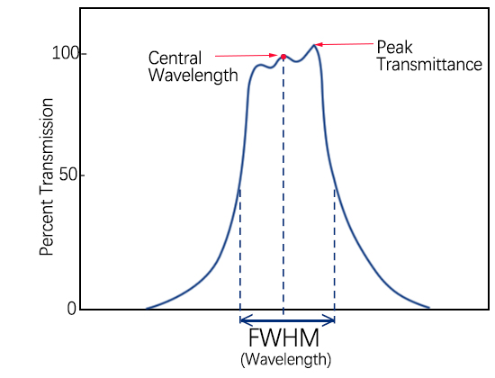
The central wavelength λc of a bandpass filter can be defined using the formula below:

Where λL, λR correspond to the wavelength positions to the left and right of the passband when the transmittance is half of the peak, respectively. The tolerance of the center wavelength is generally 20% of the bandwidth.
2. Bandwidth:
FWHM=λR-λL

4. Cutoff depth
For simplicity, the cutoff depth is
often expressed in terms of optical density (OD), and the relationship between
OD and transmittance is as follows: OD=-log10(T) For example, if T<0.01%,
the transmittance is 10-4, which corresponds to OD>4.
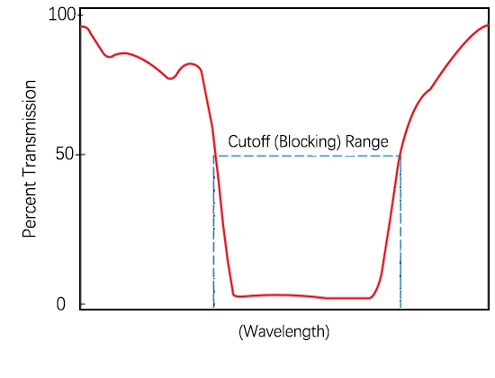
5. Cutoff range (Blocking range)

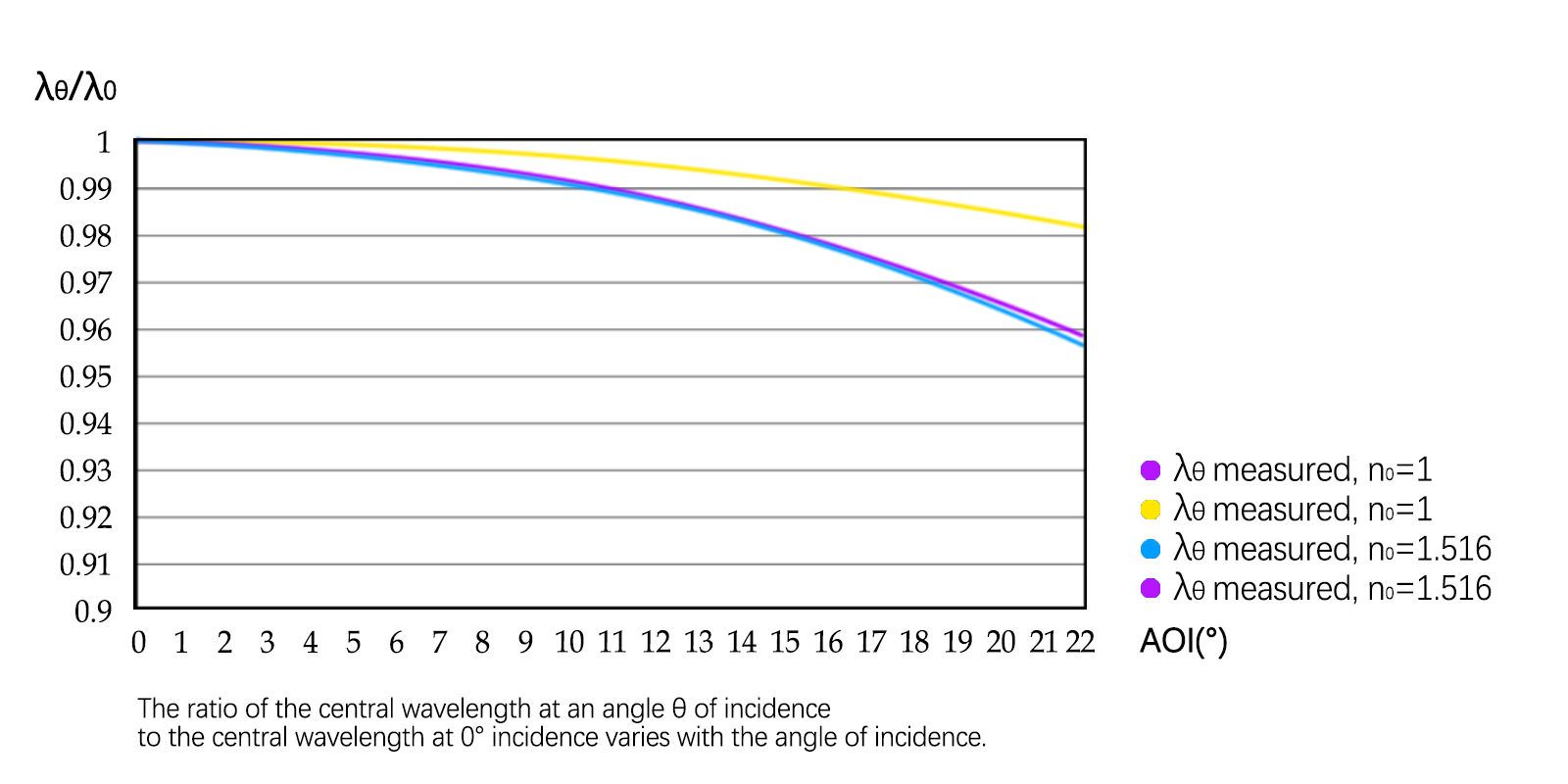
6. The central wavelength varies with the angle of incidence

neff is the effective refractive index of the narrow band filter film, related to the coatings.
For the sake of visualization, the specific values of the central wavelength shifting towards shorter wavelengths with increasing angle of incidence for two scenarios: n0=1 (narrowband filter system facing air) and n0=1.516 (narrowband filter system bonded within glass), including both theoretical and experimental values, are plotted in the following figure for reference.

7. Environmental Stability
Shalom EO strives for long-term stability and reliability in its optical filters The coating technology employed, utilizing ion-assisted electron-beam deposition, ensures that the wavelength positions of the filters remain unchanged over time. For deep UV bands below 300nm, such as 220nm, 254nm, 266nm, and 280nm, Shalom EO has adopted a unique sealing technology, which makes the service life of the filters much longer than that of conventional sealing technology.
8. Cutoff Wavelength for Longpass &Shortpass Filters
The cut-off wavelength of the long-pass filter is defined as the wavelength position where the transmittance is 50% (not 50% of the peak value);The cut-off wavelength of the short-pass filter is defined as the wavelength position point where the transmittance is 50% (not 50% of the peak value).
10. Fluorescent Filter Substrate
For filters used in fluorescent applications, Shalom EO chooses low autofluorescence glass as the coating substrate, such as UV-grade quartz glass or borosilicate glass, e.g., Schott's BF33 glass and Corning's 7980 glass are commonly used as the substrate for fluorescent filters.
Related Articles
Related Products
Tags: How to read a optical filter specification sheet?


