What are Interferomters-Principles, Types, Applications
What are interferometers-An Overview
What is an interferometer? An interferometer is a precision measurement instrument that functions based on the principle of laser interference hence the name. Invented in the mid-to late-1800s, an interferometer is potent and advanced to provide accurate measurement results in various fields including material science, geometric precision inspection, position precision inspection, etc. Moreover, interferometers are utilized on broad scales for the inspection of optics, and their outstanding excellence is in their high-precision measurements, non-contact and convenient handling mechanism, and high inspection efficiency. For one engaged in the professional realm of optics, having a thorough and comprehensive understanding of interferometers is very conducive.
In this technical article, we will be covering several topics about interferometers, including:
- an explanation of the light interference phenomenon (why does interference occur, constructive interference and destructive interference)
- the advantages and applications of interferometers
- the basic operation principle of interferometers
- different types of interferometers (including Michelson interferometer, Twyman-Green (T-G) interferometer, Fizeau interferometer, Mach-Zehnder (M-Z) interferometer, Fabry-Pérot interferometer, Sagnec interferometer).
This is a simple and comprehensible guide for beginners, aiming to help beginners build up a general understanding of interferometers, there might be several equations but that’s all, no complex mathematics is involved.
There are multiple types of interferometers. If we categorize them according to the constructions, then interferometers can be divided into two types: single-path interferometers and multi-path interferometers. The difference lies in whether the interfering waves propagate through the same path. For example, the Michelson interferometer is a common multi-path interferometer, while the Sagnac interferometer is a single-path interferometer.
Although the construction and application of different types of interferometers vary, in general, the working process of an interferometer can be simplified by explaining the basic setup of a Michelson Interferometer, which is the most classic design of interferometers. Michelson interferometer was invented in the 19/20th-century by the American physicist Albert Abraham Michelson to detect the existence of luminiferous aether that most physicists at the time believed was the medium in which light waves propagated. the basic configuration of a Michelson consists of a light source, a beam-splitter, two mirrors, and a photodetector. Light from the light source is separated by the beamsplitter into two beams that propagate in two different optical paths. The phase difference of the optical path of the test beam passing through the phase object, relative to the optical path of the reference beam, creates interference fringes when the two beams are combined again. And the interference pattern, containing information about the object or phenomenon being studied is recorded by the photodetector as an interferogram. And we can obtain the information about the object by interpreting and analyzing the interferogram.
Interference of Light
The most fundamental principle of a light interferometer is the phenomenon of light interference.
What is light interference? Light interference is a physical phenomenon that exists because of the wave nature of light. Young demonstrated interference fringes by the division of wavefronts using a double-slit experiment. When two or more trains of waves intersect and add up, interference occurs. The adding up of the waves is called Superposition. There are Destructive Interference and Constructive Interference according to the principle of superposition. The principle of superposition of waves states that when two or more propagating waves of the same type are incident on the same point, the resultant amplitude at that point is equal to the vector sum of the amplitudes of the individual waves. If the crest of a wave meets the crest of another wave of the same frequency at the same point, then the amplitude is the sum of the individual amplitudes—this is constructive interference. If a crest of one wave meets a trough of another wave, then the amplitude is equal to the difference in the individual amplitudes—this is known as destructive interference.
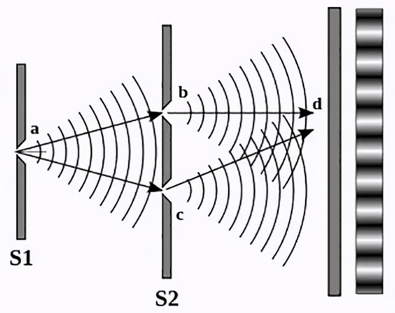
Figure 1. Light from the source a passing two slits b and c creates an interference pattern with dark and bright stripes
This is easy to understand when you imagine it as throwing stones into a pond, the behavior of water waves is very similar to light waves. When the stones reach the water, there are concentric ripples expanding from the source, and the waves will interact with each other. When two crests coincide, there will be a larger wave. When the peak of one wave meets with the trough of the other, the waves cancel each other out and the surface is flat. In practice, it is very rare that the waves are exactly the same. However, just remember that when the waves superpose, the resultant amplitude is always the sum of the heights and depths wherever they meet.
The same ideological model can be applied to light because light exhibits wave nature just like water. when two beams of laser light merge, they too generate an interference pattern that depends on how well-aligned the light waves are when the light beams combine. The same as water, light waves will be strengthened when the wave crests coincide, and the result will be greater brightness; but when the crests meet troughs, the light waves will offset each other, and the result will be lower brightness.
To further explain interference, we can introduce the concept of phase. Phase is the position of a wave in its cycle at a particular moment: a measure of whether it is at a crest, a trough, or some point in between. Phase measure of the change in a signal waveform, usually in degrees (angles), also called phase angle. When the signal waveform changes in a periodic manner, one cycle of the waveform is 360°, or 2π. The core principle of the interferometer is to acquire the phase information of the wave, thereby obtaining the physical quantity of interest. Phase difference determines how waves interact and thus the resultant interference pattern.
Destructive interference is shown in the figure 2 below. Assume that when the highest value of the blue wave and the lowest value of the red wave are of the same amplitude 1, because light has wave characteristics, if the crests of red waves and the crests of the blue waves are half the wavelength apart from each other, that is, when the phase difference is π, their sum value of the two waves is 0, so when the two blue and red waves add up the result will become a flat line, the picture will appear completely dark and interference pattern cannot be seen at all. This is called destructive interference.
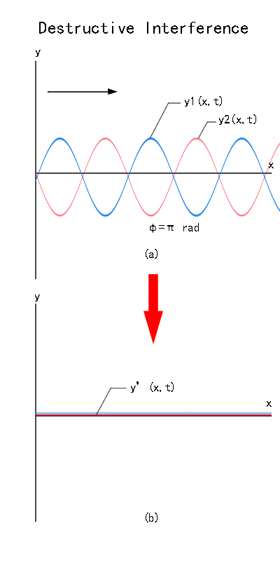
Figure 2. Complete destructive interference
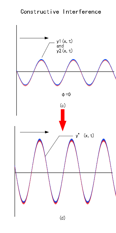
Constructive interference is shown in the figure 3 below. Assume that when the highest points of the blue wave and the red wave are of the same amplitude 1. When the blue wave and the red wave completely overlap (they are in phase), the superposition forms the black line in the figure below, their sum value is 2. When we observe the interference pattern with the naked eye, the highest point of the black line will become brighter and the lowest point will be darker. There will be changes in light and dark lines. We call it constructive interference.
Figure 2. Constructive interference
The Operation Principles of Interferometer
Interference: As explained above, the fundamental principle of the interferometer is interference. When two or more light waves overlap, the waves combine to form a new interference pattern. Interferometers extract information by interpreting the interference patterns.
Light Source: A light source is needed for the generation of an interference pattern. Nowadays, Interferometers typically use a coherent light source, such as a laser, which emits light waves that are in phase and have a consistent wavelength.
Splitting and Recombining Light: An interferometer splits a single light beam into two or more paths using a beam splitter. These beams travel different paths and are then recombined to produce an interference pattern.
Path Difference: The split beams travel along different paths, which may involve reflecting off mirrors or passing through different media. The length of these paths is typically adjustable.
Detection and Analysis: The interference pattern is observed and analyzed. Changes in the pattern can indicate changes in the path length difference or other properties being measured.
Why are interferometers so useful?
The advantages of interferometers are manifold. The first advantage that making an interferometer is its high precision, which is critical for the quality control of optical components. Optics require exactitude, minute variations of the specifications in optical components could have serious detrimental effects and consequences on the quality of products, and measuring instruments of extreme precision are necessary. Interferometers have the advantage of exceptional precision, up to 1/100 wavelength (the wavelength here refers to 632nm which is common the wavelength of the light source used for interferometers). The precision can even reach 1/1000 of the wavelength. We can do a simple calculation, for example, the wavelength of a general standard interferometer is 632.8 (nm), and one hundredth of 632.8 is about 6 (nm). From this, we can get a quick idea of how precise and accurate an interferometer is.
The second appealing attribute is non-contact measurement. Compared with some other types of profilometer used for measurement, which incorporate a contact measurement mechanism, the merit of the interferometer is obvious. Because with a contact measurement mechanism, it is really hard to determine whether the contact force will cause damage if the tested piece is very fragile. When measuring with an interferometer, light is irradiated onto the object being measured, so contacts and therefore possible damages and injuries to the surface of the object are avoided during the measurement procedure.
Third, what makes interferometers so useful is their fast measuring speed. When using a probe to measure, it is impossible to measure the entire area at once, and it might be necessary to divide many scanning lines for measurement. Relatively speaking, the measurement speed of the interferometer will be faster, and the measurement may be completed in a few seconds.
What are interferometers used for-The Applications
The application range of interferometers is extensive, including but not limited to:
Length Measurement:
In a double-beam interferometer, if the refractive index of the medium is uniform and constant, the movement of the interference fringes is caused by the change in the geometric path distance of the two coherent lights. According to the movement number of the fringes, an accurate comparison or absolute measurement of the length can be made. The Michelson interferometer and the Fabry-Perot interferometer were used to represent the international meter in terms of the wavelength of the cadmium red line.
Refractive Index Measurement:
The geometric paths of the two beams remain unchanged, and changes in the refractive index of the medium can also lead to changes in the optical path difference, thus causing fringe movement. The Rayleigh interferometer is a typical interferometer that performs relative measurements of refractive index through fringe movement.
Measurement of Wavelengths:
Fabry-Perot interferometers (etalons) were used to determine a primary standard of wavelength (the wavelength of the cadmium red spectral line) and several secondary wavelength standards to determine the wavelengths of other spectral lines by comparison.
Inspection of Optical Components:
The Twyman-Green interferometer, which is a variant of the Michaelson interferometer, is commonly used to inspect the quality of optical components such as plates, prisms, and lenses. When a plate or prism to be inspected is placed in one of the optical paths of the Twyman-Green interferometer, any non-uniformity in the refractive index or geometric dimensions of the plate or prism will be reflected in the interference pattern. If a lens is placed in the optical path, the wavefront distortion caused by the lens can be analyzed based on the interference pattern, therefore the wave aberration of the lens can be evaluated.
Gravitational Wave Measurements:
Interferometers can also be used for gravitational wave detection (Saulson, 1994). The concept of laser interferometer gravitational wave detector was proposed by former Soviet scientists Gertsenshtein and Pustovoit in 1962. In 1969, American scientists Weiss and Forward built preliminary test systems at MIT and Hughes Laboratory respectively (Weiss 1972). As of today, laser interferometer gravitational wave detectors have been developed for more than 40 years. The current LIGO laser interferometer experiment claims to have directly measured gravitational waves for the first time (LIGO collaboration 2016).
Types of Interferometers
One can categorize the interferometer into many types according to the construction of the interferometers. The main types of interferometers include the Michelson interferometer, Twyman-Green (T-G) interferometer, Fizeau interferometer, Mach-Zehnder (M-Z) interferometer, Fabry-Pérot interferometer, Sagnec interferometer, etc. In general, most of the instruments are two-beam interferometers whereas the Fabry-Pérot (F-P) interferometer is based on multiple-beam interference. This article offers a simple explanation of the configurations, the operation principles, the characteristics, and the applications of different types of interferometers.
- Michelson Interferometer
The classic interferometer design, with two perpendicular arms. It is invented by Albert A. Michelson. He first developed the equipment to carry out the famous “Michelson-Morley experiment” in the attempt to prove that the earth’s motion is attributed to a theoretical matter called aether that was hypothesized to support the propagation of light waves in our universe.
A Michelson Interferometer consists of a light source (it is often a laser as a quasi-monochromatic light source, using a single transverse mode laser beam, approximating a Gaussian beam is advantageous), two mirrors at minimum, a beam splitter (although a diffraction grating or a half-silvered mirror is also used), and a detector.
The operation principle is stated as follows: As shown in figure 4 below, the light source emits light that hits the beam splitter (or a half-silvered mirror) at the original point C. The beamsplitter splits light into two parts with perpendicular directions, transmitting part of the light to mirror 1 while some are reflected in the direction of mirror 2. Both beams recombine at point C' to produce an interference pattern incident on the detector at point E. There will be constructive or destructive interference as long as there is a non-zero path difference between the optical paths of the beam reflected by mirror 1 and the beam reflected by mirror 2. Since the beams are from the same source, their phases are bound to be correlated. When a sample lens is placed between the laser source and beam-splitter, the light spreads out, and an interference pattern of dark and bright rings, or fringes, is seen on the viewing screen. This process is known as interference by division of amplitude.
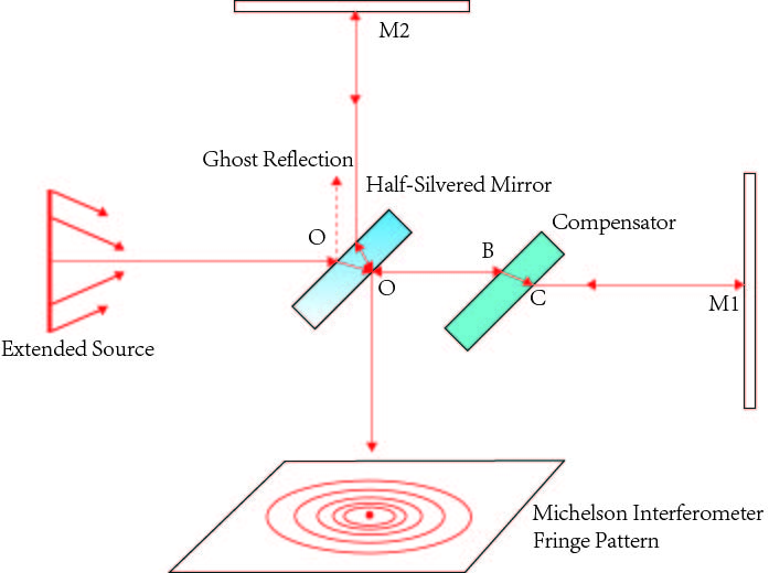
Figure 4. The setup and operation of the Michelson interferometer
A linear optical counterpart of the Michelson interferometer aids in comprehending the differences in optical paths (figure 5). The mirror M1 is substituted with its virtual image M1I, observed when looking through the beam splitter from the source's perspective. The source aperture is replaced by its virtual image SI, seen when looking into the beam splitter from mirror M2's position. The resulting interference pattern detected is identical to that which would be produced by a source SI reflecting off two separate mirrors, M2 and M1I, positioned apart from each other by a length of △d=|d1-d2|
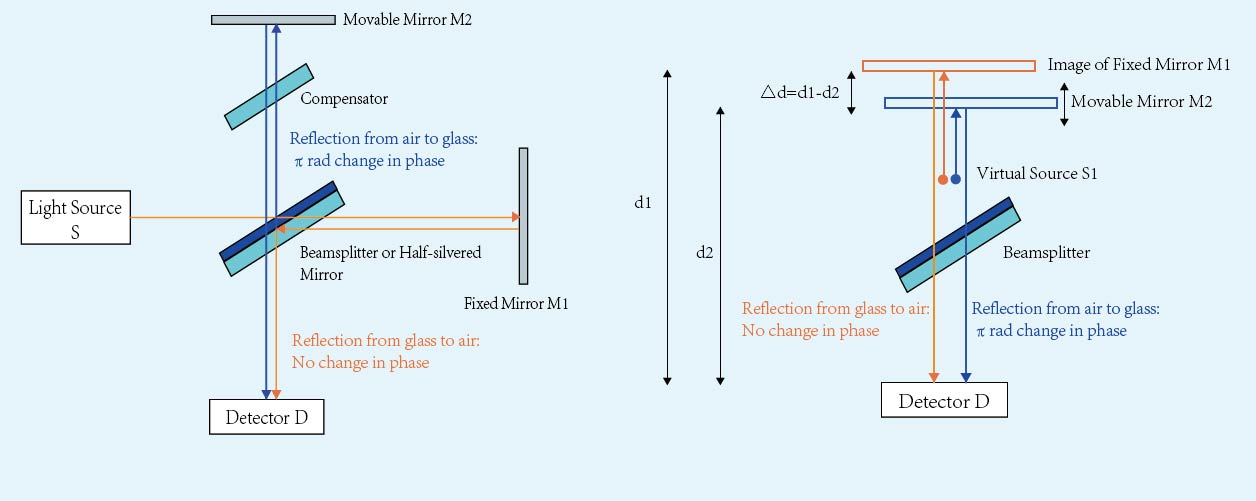
figure 5. optical path difference resulting from reflection in Michelson interferometer
The optical path difference between the light reflected from the two mirrors M1I and M2 is |△2d|. The equations for destructive and constructive interference are as follows:
Destructive Interference: |△2d|=nλ, n=0, 1, 2, 3, 4, ...
Constructive Interference: |△2d|=(n+1/2)λ
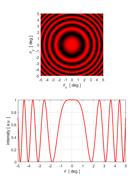
If the mirrors are precisely aligned so their planes are perpendicular to each other, the fringe pattern will be a series of concentric rings. Each ring corresponds to a different angle of view, measured from the normal to mirror M1. These are called fringes of equal inclination. If the light source is a point source, the fringes will be circular. If the interferometer is fed with a parallel beam of light, the fringes will be of equal thickness. If the mirrors are inclined at an angle, the fringes will be straight or conic. In the interference of light waves, energy is redistributed, and the light energy at the destructive interference position is transferred to the constructive interference position, while the total energy always remains conserved.
Figure 6. Michelson interferometer fringe pattern
Note that the number of times the two beams of light pass through the beam splitter during the interference process is different. The beam of light reflected from the right mirror only passes through the beam splitter once, while the beam of light reflected from the upper mirror passes through the beam splitter three times. This will lead to changes in the optical path difference between the two. For the interference of monochromatic light, this does not matter, because this difference can be compensated by adjusting the length of the interference arm; but for polychromatic light, due to the dispersion of different colors of light in the medium, this often requires adding additional light on the path of the right plane mirror. A compensating plate made of the same material and thickness as the beam splitter can eliminate the optical path difference caused by this factor, the compensating plate can also compensate for the temperature dependence.
Michelson interferometer is often used to measure minute lengths, refractive index, wind and temperature patterns, and wavelength of light waves. The Michelson interferometer also serves as the basis of the Laser Interferometer Gravitational-Wave Observatory (LIGO).
- Twyman–Green Interferometer
The Twyman-Green Interferometer was invented in 1916 by British physicists Frank Twyman and Alfred Green. Their goal is to improve the Michelson interferometer so that it can measure larger beams and thus improve measurement accuracy. A major advantage of this interferometer is that it can directly measure the deviation of a light wavefront without comparing two adjacent light wavefronts.
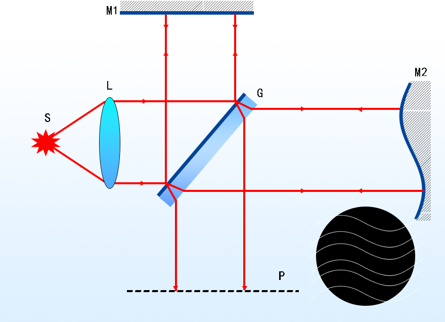
The Twyman-Green Interferometer can be regarded as a variation of the Michelson interferometer because their optical setups are very similar, the Twyman-Green Interferometer also comprises a light source, one beamsplitter, two mirrors, but in the case of a Twyman-Green interferometer, the light beam from the light source (the light source is often a single wavelength laser) is collimated and expanded to a substantial diameter, this means the Twyman-Green interferometer can measure the deviation of the entire light wavefront simultaneously, not just one point each time. The beam splitter splits the beam into two components: the reference beam and the test beam. The “reference beam” is directed to a high-quality reference mirror. The “test beam” is directed to the test surface. The test wavefront can be shaped to match the concave/convex curvature of the test surface by using a diverging lens or beam expander.
Figure 7. Twyman-Green interferometers-basic setup and interference pattern
The second difference between the Twyman-Green interferometer and the Michelson interferometer is that the Twyman-Green interferometer contains a lens to correct the aberration, the third difference is that the Twyman-Green interferometer does not have a compensating plate.
The operation principle of the Twyman-Green interferometer and the Michelson interferometer is identical: the difference in the optical paths of the arms generates an interference pattern on the detector. The object under test or the reference mirror is mildly tilted on purpose e.g. by turning a micrometer screw, an interference pattern with regular stripes having an appropriate spacing can be acquired. These stripes are perfect lines if the test surface is as precise as the reference surface. Imperfection of the surface shapes results in distortions of those stripes (Fizeau curves).
The critical parameters of the Twyman-Green interferometer include the wavelength of the light source, the reflectivity of the beam splitter, and the resolution of the interference pattern. These parameters all affect the performance of the interferometer. For example, the shorter the wavelength of the light source, the higher the resolution; the higher the reflectivity, the more obvious the interference pattern.
The Twyman-Green interferometer can be divided into two types: static and dynamic. During the measurement process of a static interferometer, the light source, interferometer, and the object being measured remain stationary. The dynamic interferometer allows for changing the position of the light source or the object being measured during the measurement process, thereby achieving dynamic measurement.
The Twyman-Green interferometer is often used to test the quality of optical systems such as lenses, mirrors, and telescopes, as well as to quantify the wavefront aberrations present in these systems. They can be used to test the properties of materials, such as the stress and strain present in a sample, by measuring the phase shift in the interference pattern produced by the interferometer. They are used to perform high-resolution microscopy, as well as to measure the size and shape of small particles and other structures.
- Fizeau Interferometer
A simpler version of the Twyman-Green interferometer would be the Fizeau Interferometers, which are also used for characterizing optical surfaces. The Fizeau interferometer is an optical instrument invented by French physicist Hippolyte Fizeau. The Fizeau interferometer consists of two reflective surfaces. The Fizeau interferometer is a prevalent option for the measurement of the quality of optical components and systems, a typical example is the measurement of the shape of optics. In the measurement process, a reference piece with high precision is placed on top of the sample being tested, in this manner, one can exploit interference between reflections at a test surface and the reference surface. In general, the Fizeau interferometer is capable of characterizing optical surfaces with nanometer precision, providing a guide for the manufacturing of components, an aid for alignment, and a validation of system performance.
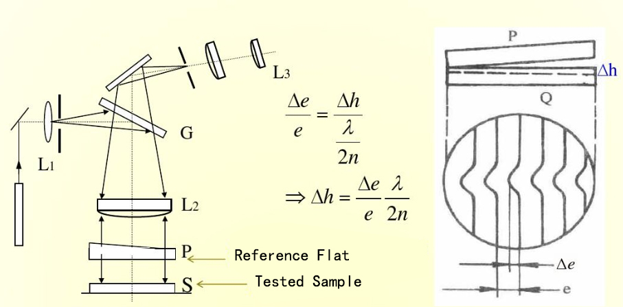
Figure 8. The setup of a Fizeau Interferometer, where G is the beamsplitter, P, the reference flat, is placed on top of the S, the tested sample.
Its advantage is that interference occurs only between two parts at close distance, and only the relative distance of those last be altered with care. The orientation of the beam splitter, for instance, is not important. On the other hand, the Twyman–Green interferometer is more flexible, e.g. regarding the optimization of fringe contrast for different reflectivities of the investigated samples.
- Mach-Zehnder Interferometer
The Mach–Zehnder Interferometer is an interferometer that can be used to observe the relative phase shift changes between two collimated beams. The instrument was named after the German physicists Ludwig Mach (son of Ernst Mach) and Ludwig Zendel.
The Mach-Zehnder Interferometer contains two beamsplitters and two mirrors. The first beamsplitter splitter splits the incoming light into two beams with equal optical path lengths, which is the distance traveled times the refractive index of the media in which the light propagates. The two beams are reflected by the mirrors and recombined by the second beamsplitter and redistributed to two detectors.
Now before we go deeper to explain the working principle of the Mach-Zehnder interferometer we must understand the following facts: There is a phase change for a reflection when a wave propagating in a lower-refractive index medium reflects from a higher-refractive index medium, but not in the opposite case. The index of refraction of a perfect mirror can be thought of as infinite. Thus light reflected by a mirror has its phase changed by one-half a wavelength. When a light beam goes from one medium into another, its direction changes due to refraction but no phase change occurs at the surfaces of the two mediums.
Now name the two detectors detector A and detector B, and there are two paths C and D in which light travels. First consider light entering detector A via path C and path D. After calculation based on the rules mentioned above we can the light reaching detector A via path C and path D is in phase, therefore there is constructive interference for light entering detector 1.
Considering light reaching detector B, there is a path difference of one-half λ for path C, therefore the light will be canceled out, and no light will enter detector B.
Now place a test sample either in path C or path. The sample introduces a phase change and changes the original phase relationships between the two beams that we described above, and there is no longer complete destructive interference at detector B. Measuring the relative amount of light entering detector A and detector B allows a calculation of the phase shift produced by the sample.
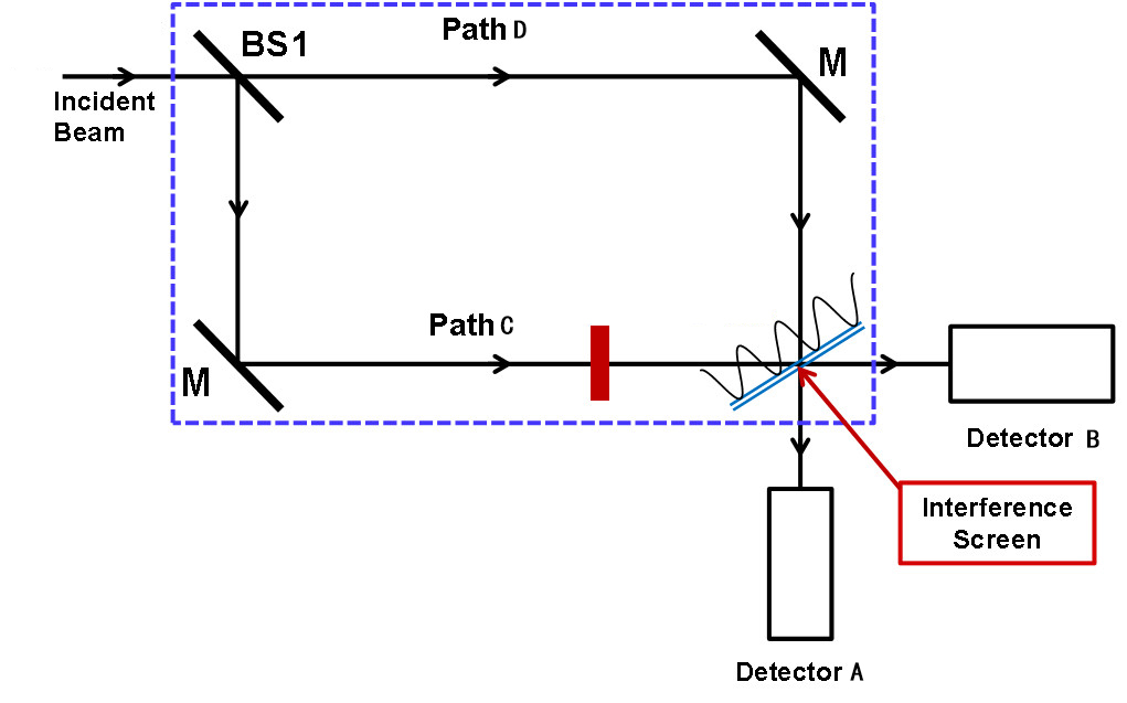
Figure 9. A light beam travels two separate paths and reaches two detectors in a Mach-Zehnder Interferometer
The Mach–Zehnder interferometer has the advantage that the separation of the two beams can be made as large as desired and the test section is traversed only once. In addition, white-light fringes can be obtained and localized in the same plane as the test section.
The application range of the Mach-Zehnder interferometer is broad, including optical modulators to encode information onto a light beam by varying the phase of the light, measuring small changes in temperature, pressure, or refractive index by observing changes in the interference pattern, and signal processing. The Mach-Zehnder interferometers are also used in the field of quantum mechanics in experiments to demonstrate the principles of quantum superposition and entanglement.
- Fabry-Pérot Interferometer
Named after Charles Fabry and Alfred Pérot, the Fabry-Pérot Interferometer (also known as Fabry-Pérot resonator) is an optical resonator consisting of two parallel, planar glass plates. The Fabry-Pérot interferometer is used as a high-resolution spectrometer, it is capable of detecting and resolving the fine features of a transmission spectrum with high precision and, therefore often utilized to determine the resonant modes of laser cavities.
The Fabry-Pérot interferometer operates based on the principle of multiple beam interference, which presents when multiple coherent beams of light interact with each other, resulting in the formation of an interference pattern.
The glass plates (or mirrors) have an air gap between them and their inner surfaces are coated with high-reflection coatings (a common example of the reflection rate would be 80%, therefore the glass plates transmit part of the light as well). A monolithic variant of this design would be a glass plate with reflective coatings on both surfaces. In a strict sense, the glass plates or mirrors in a Fabry-Pérot interferometer should be planar, nevertheless, spherical mirrors are also common. What happens is that a large number of reflections takes place between the glass plates, each reflection forms constructive interference or destructive interference with previous reflections, depending on the path length difference and the wavelength of the light. The large number of interfering waves produces an interferometer with high resolution, somewhat like the multiple slits of a diffraction grating increase its resolution.
The glass plates are positioned perpendicular to the optical axis. Figure 10 shows how a fabry-perot interferometer operates. A light beam from a light source O is incident at an angle α on the interferometer. Attributing to multiple partial reflections between the glass plates, a set of parallel transmitted beams exit on the other end of the glass plates. These are then focused at point C at the focal plane of the converging lens B. In a similar manner, all the incident beams from the other points of the source, inclined at the same angle α, are also focused at C. This generates concentric fringes on the screen with lines that are equal spaces apart.
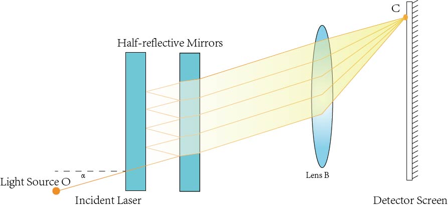
Figure 10. Fabry-Pérot Interferometer
The conditions for maximum or minimum at C can be calculated using the equations:
Maximum: △=2tcosα=mλ
Minimum △2tcosα=(m+1/2)λ
Where t is the thickness of the air gap, α is the angle of incidence, λ is the wavelength of the light source, and m is an integer.
By adjusting the length of the air gap, t, one can select specific wavelengths of light for transmission or reflection.
The Finesse (F) of the Fabry-Perot interferometer is a measure of its ability to resolve spectral lines. The higher the reflectivities, the higher the finesse of the Fabry-Pérot interferometer, the sharper the transmission peaks.
Compared to the Michelson interferometer, the Fabry-Pérot interferometer can achieve higher resolution due to the multiple reflections and interference. Besides the applications in high-resolution spectroscopy, the Fabry-Pérot Interferometer can also be used in astronomy to study the properties of celestial objects such as stars and galaxies, employed in telecommunications and other fields to create optical filters that transmit specific wavelengths while blocking others. High-finesse Fabry–Pérot interferometers are used as reference cavities and for spectral analysis.
- Sagnac Interferometer
The Sagnac Interferometer, also known as the Ring Interferometer is an optical device that relies on the interference of light to detect rotation. Named after French physicist Georges Sagnac, it is particularly well-known for its application in ring laser gyroscopes and fiber optic gyroscopes, which are used in navigation systems. When first invented, the aim of Georges Sagnac (1869–1926) was to observe the correlation of angular velocity and optical phase shift. The Sagnec interferometer operates based on the Sagnec Effect, which refers to the phenomenon where a rotation of a structure, can cause a phase shift in the interference fringes produced when the divided beams recombine (relative phase shift between two beams of light that travel on an identical path in opposite directions within a rotating frame).
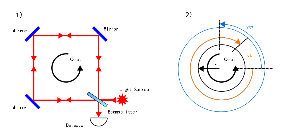
A Sagnac interferometer consists of a beam splitter (half-silvered mirror), three corner mirrors, a light source, and a detector, or in some cases, the light traveling in the circulating path can also be guided by optical glass fiber.
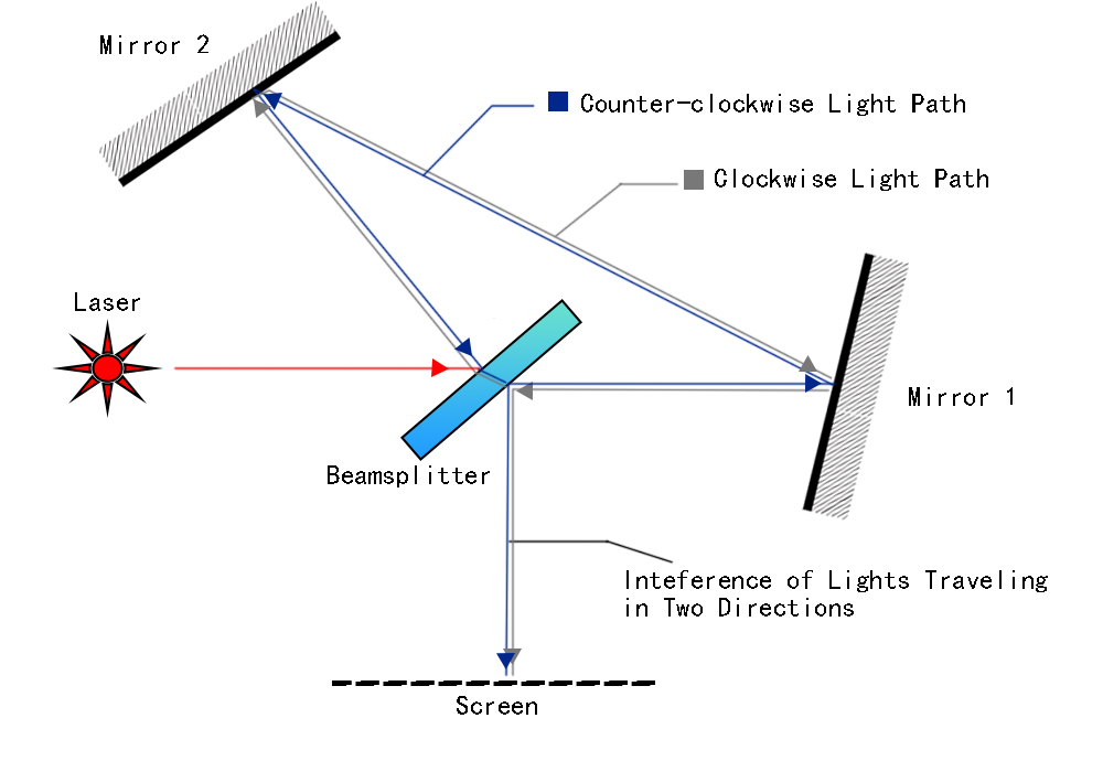
Figure 11. The basic structure of a Sagnec interferometer
The light beam is split into two beams. The two beams travel around the loop in opposite directions (clockwise and counterclockwise). Mirrors or fiber optics guide the beams along the loop path. After traversing the loop, the beams are recombined at the beam splitter, resulting in an interference pattern. The core principle of a Sagnec interferometer is that the relative velocities of light beams traveling in different directions are different when the interferometer rotates. For the observer, light traveling in one direction will be faster than light traveling in the opposite direction when the interferometer is rotating. The difference in the velocities of the two beams generates phase shifts between the two light beams, and the phase shifts lead to changes in the interference pattern. Because the interference pattern shifts in response to rotation, the amount of shift in the interference fringes is proportional to the rate of rotation of the loop.
Figure 12. Rotation and interference in a Sagnec interferometer
When the entire interferometer, including the light source and the fringe detector, is rotated at an angular velocity of Ω rad/sec, a fringe shift Δφ with respect to the fringe position for the stationary interferometer can be spotted, and the equation for the fringe shift is:
Δφ=(4A*Ωrot)/λ0c
Where A is the enclosed area of the light path,λ0 is the vacuum wavelength and c is the free space velocity.
The Sagnac interferometer has the advantages of vibration resistance and the control of the absolute difference in the length of the arms of the interferometer. Applications of the Sagnac Interferometer include navigation-ring laser gyroscopes (RLGs) and fiber optic gyroscopes (FOGs) for precise measurement of rotational rates. These gyroscopes are essential components in inertial navigation systems for aircraft, ships, submarines, and spacecraft.; geophysics:-used to measure the rotation of the Earth and for seismic studies; fundamental physics: applied in experiments to test the principles of relativity and to study rotational dynamics, and stabilization systems: Used in stabilization systems for cameras and other equipment that require precise control of orientation.
Inspection Procedure in Shalom EO using Interferometers
At Shalom EO, our core values of quality assurance and customer confidence drive us to implement stringent quality control procedures. Every product undergoes meticulous inspection in our Class 100000 clean room before it is packed and shipped.
Utilizing interferometers forms a crucial part of our quality control process. To obtain authentic results, we introduce Zygo interferometers (which are an industrial-recognized authoritative brand ) These advanced instruments provide precise results for e.g. testing the curvature radius and surface flatness of optics and components. In our inspection lab, all measurements are carried out by Shalom EO’s specialized quality control team, led by an expert with over 20 years of professional experience in optical testing.

Figure 13. Flatness of Super Polished Surface Measure by Zygo Interferometer
(Fused Silica Substrate of Diameter 300mm, PV=0.101 Wave @633nm)
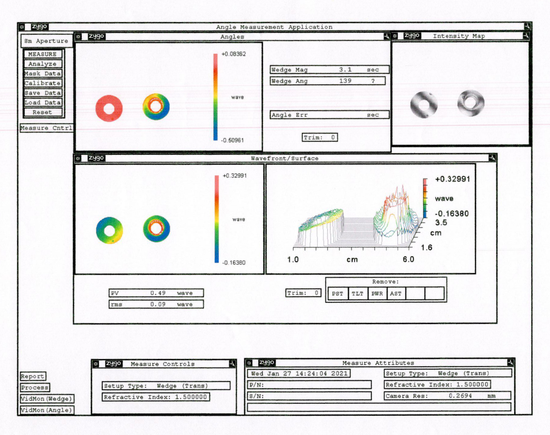
Figure 14. shows the inspection results of optical components with drilled holes using the Zygo interferometer
We adhere to a comprehensive manual with detailed instructions on the proper use and maintenance of our interferometers. Furthermore, regular calibration of the interferometers ensures consistent accuracy and reliability. This commitment to precision and thoroughness in our inspections solidifies Shalom EO’s reputation for excellence in the optical industry.
Tags: What are Interferomters-Principles, Types, Applications


